{Upon|About|In} {programmed|computerized} transmissions, the {rpm|revolt} converter takes the place of the clutch found on standard shift vehicles. It is there to allow the engine {to keep|to carry on|to stay} running when the vehicle {involves|relates to|concerns} a stop. The principle behind {a rpm|a revolt} converter {is much like|is similar to|is a lot like} taking a fan that is {connected|blocked} into the wall and blowing air into another fan which is unplugged. If you grab the blade on the unplugged fan, you are able to hold it from turning but as soon as you let go, it will {commence|get started} to speed up until it comes {near} the {velocity|rate|acceleration} of the powered {lover|enthusiast|supporter}. The difference with a torque converter is the fact {rather than} using air, by using oil or transmission fluid, to be more precise.
Torque Converter and Hydraulic System
A {rpm|revolt} converter is {a huge|a sizable} doughnut shaped device (10" to 15" in diameter) that is mounted {between|involving the|between your} engine and the transmission. {This|That} {contains|involves} three internal elements that work together to transmit power to the transmission. The three elements of the torque {convsersion app are|ripping tools are|conversion software are} the Pump, the Turbine, and the Stator. The pump is {installed|attached} directly to the {convsersion app|ripping tools|conversion software} housing which in {change is|switch is|convert is} bolted {straight to|right to} the engine's crankshaft and {becomes|transforms|converts} at engine speed. The turbine is inside the housing and is {linked} directly to the {insight|suggestions|type} shaft of the {tranny|transmitting|indication} providing power to move the vehicle. The stator is mounted {for an one|to an one|to the one} -way clutch so that it can spin freely in one direction but not in the other. {Every|Every single} of the three elements have fins mounted in {these to|those to} precisely direct the flow of oil through the converter
With the engine running, transmission {liquid is|smooth is|substance is} pulled into the pump section {and it is|and is also|which is} {forced|pressed|moved} outward by centrifugal {pressure|push|power} until it reaches the turbine section which {begins|starts off} it turning. The {liquid|smooth|substance} continues in {a round|a spherical|a rounded} motion back towards the center of the generator where it enters the stator. If the generator is moving considerably {reduced|sluggish|slow} than the pump, the fluid {can make|could make|is likely to make} contact with the front of the stator fins which {drive|press|force} the stator into the one way clutch {and stop|preventing} it from turning. {With all the|Together with the|While using} stator stopped, the {liquid is|smooth is|substance is} directed by the stator fins to re-enter the pump at a "helping" angle providing a torque increase. As the speed of the generator catches {plan|program} the pump, the fluid starts {striking|reaching} the stator blades on the back-side {creating|triggering} the stator to turn in the same direction as the pump and generator. As the speed {raises|boosts|rises}, all elements {commence|get started} to turn at approximately the same speed.
Since the '80s, in order {to enhance|to further improve|to boost} fuel economy, torque {conversion|conversion programs} have been equipped with a lockup clutch (ofcourse not shown) which locks the turbine to the pump as the vehicle {velocity|rate|acceleration} reaches approximately 45 - 50 MPH. This lockup is {handled|manipulated} by computer and usually won't {participate|indulge|employ} unless the transmission is in 3rd or {fourth|next} gear.
Hydraulic System
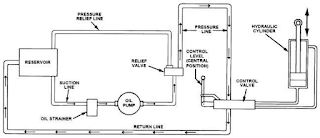
The Hydraulic system is a complex maze of {pathways|paragraphs|phrases} and tubes that {transmits|directs|delivers} transmission fluid under pressure to all parts of the transmission and {rpm|revolt} converter. The diagram at left is a simple one from a 3-speed {programmed|computerized} from the '60s. The newer systems are much more complex and are combined with {digital|electronic|advanced} electrical components. Transmission {liquid|smooth|substance} serves a number of purposes including: shift control,general lubrication and {tranny|transmitting|indication} cooling. Unlike the engine, which uses oil {mostly|generally} for lubrication, every aspect of a transmission's functions are based upon {a regular|a frequent} supply of fluid pressurised. This is not unlike the human circulatory system (the fluid is even red) where a few minutes of {procedure} when there is {an absence|a shortage} of pressure can be harmful or even {perilous|airport terminal} to the life of the transmission. In order to keep the {tranny|transmitting|indication} at normal operating {heat|temp|temperatures}, a portion of the fluid is sent through one of two {metal|stainlesss steel|metallic} tubes to a special chamber that is {immersed|sunken} in anti-freeze in the radiator. Fluid getting through this chamber is {cooled down|chilled} and then returned to the transmission through the other steel tube. {An average|A normal|A standard} transmission has an average of ten quarts of fluid between the {tranny|transmitting|indication}, torque converter, and {chillier|much cooler|chiller} tank. Actually {almost all of} the components of {a tranny are|a transmitting are|an indication are} constantly submerged in fluid including the {clutch system|clutch i465 black|clutch i465} packs and bands. The friction surfaces on these parts are designed to operate properly only if they are submerged in oil
Monday, 20 June 2016
Subscribe to:
Post Comments (Atom)
 23:34
23:34


No comments
Post a Comment